John H. Kerr Project was built by the U.S. Army Corps of Engineers, Norfolk District, and is now operated by the Wilmington District.
Construction was authorized by the seventy-eight Congress on 22 December 1944, with work commencing in March 1947. Completion date was early 1953.
The primary functions of John H. Kerr Project are flood control and production of hydroelectric power. The Project also provides benefits such as wildlife resources, forest conservation, and public recreational uses. Besides the control of floods, the project provides other benefits downstream from the dam through the regulation of flows for water quality control and maintaining river levels for fish spawning. Twenty feet of storage is reserved for flood and is designed to control the largest flood on record.
Kerr Dam generates an average of 426,749,000 kilowatt hours per year, which is sold to local power companies for local consumption. Since construction Kerr Dam has prevented over $385,638,000 in downstream flood damages.
At the beginning and early stages of construction, the project was called Buggs Island Lake. Buggs Island is the name of the Island immediately downstream from the dam and was named after Samuel Bugg, an 18th century pioneer. The name of the project was changed to John H. Kerr Dam and Reservoir by the eighty-second Congress in 1951. John H. Kerr was a Congressman from North Carolina who was instrumental in Congress authorizing the construction. The site was selected for the strong solid granite foundation needed to support the heavy concrete and the availability of rock for construction.
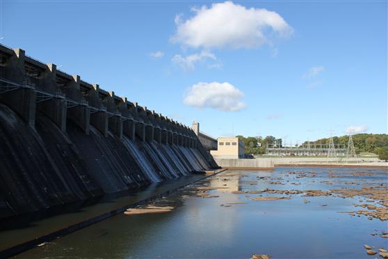
The John H. Kerr Project consists of a dam, powerhouse, and switchyard. The Dam is of the gravity type composed of the spillway, intake, and non-overflow sections, an earth-fill wing, and saddle dikes. It was built in 53 sections called monoliths. The joints between the monoliths were sealed to prevent leakage.
A grouting tunnel was built in the dam from end to end following the contour of the bedrock. In this tunnel, holes were drilled into the bedrock and concrete was forced under pressure to fill all cracks and crevices in the rock and between the rock and concrete. Drilled Holes were left open to relieve any water pressure that may seep between the concrete and rock. The tunnel also removes any leakage between expansion joints. Total leakage into the tunnel averages between 7 to 10 gallons per minute.
Twenty-two floodgates were built in the overflow section. Any floodwaters in the reservoir above the elevation 300 feet are either sold as electrical energy or spilled through these gates.
Erosion is prevented at the toe of the spillway by deflecting the floodwater upward in a trough called a bucket. Retaining walls were built on each end of the spillway to direct the flow of the discharged water.
Six sluices were built in the base of the dam. These were used to discharge a minimum flow of water downstream during impoundment that was required for about six months during construction.
Water to drive the turbines flows through penstocks into a scroll case. The water then passes through the governor controlled gates into the turbine and is discharged into the tailrace through draft tubes and tunnels that deflect the water upward.
The turbine is connected to the generator by a shaft 35 inches in diameter. There are seven generators capable of producing up to 227,000 kilowatts of pollution-free power and two generators used for in-house power production. The speed at which the large units rotate is 85.7 RPM. The large turbines produce 45,000 HP and small turbine 17,000 H.P at 90-foot head. Plant efficiency averages about 83%. Each large generator is rated at 32,000 kilowatts and the small one at 12000 kilowatt. The Westinghouse generators produce electricity at 13,800 volts that is conducted by copper conductors to the transformer. The transformers step up the volts to 115,000 volts and the electricity is conducted by copper wire through tunnels to the switchyard. Here, all electric powered generated is conducted onto a common high voltage bus and from this bus six transmission lines transmit power to the Virginia Power and CP& L power companies. Fifty-eight per cent of the power sold goes to Virginia Electric Power Company and forty-two per cent to the Carolina Power and Light Company. About one half of the power is transmitted to various government preference customers such as rural Cooperatives.
The bottom or " Dead Storage" portion of the reservoir remains full at all times in order to provide the minimum water pressure necessary to operate the power plant. The middle or " Power Storage" portion is used for the production of electrical energy and for regulation of stream flow below the dam. The top or & Flood Storage" portion is reserved for storage of flood waters and will remain empty most of the time.
Stored water may pass the dam in three ways, namely: (1) through the powerhouse turbines by means of large conduits or penstocks, (2) over the spillway which is controlled by 22 large tainter gates, and (3) through 6 sluices at the base of the dam. A flip bucket at the foot of the spill way dissipates the destructive energy of the water and prevents erosion of the foundation of the dam. Concrete training walls direct the flow of water into the river channel below the dam.
To generate hydroelectric power, water from the reservoir flows through the gate-controlled penstocks, rotates the turbines in the powerhouse and discharges through the draft tubes to the river channel below. The turbines are directly connected to generators which produce electric power. The electric current is increased in voltage by large transformers for transmission away from the project.